


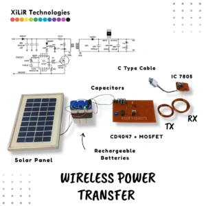

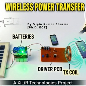
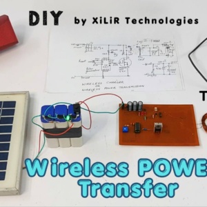
Solar based Wireless Power Transfer (WPT) Project


Original price was: ₹7,650.00.₹5,850.00Current price is: ₹5,850.00.
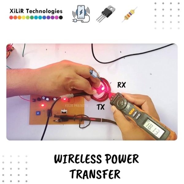
Wireless Power Transfer System using Inductive Coupling enables contactless energy transmission through magnetic fields for efficient wireless charging of electronic devices. This circuit-based project uses oscillator, MOSFET driver, and transmitter–receiver coils to demonstrate real-time wireless power transmission with compact and efficient design.
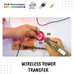
—If coils are properly aligned → ⚡ Wireless Power Transfer Active
—If receiver enters magnetic field range → ✅ Power Transmission Successful
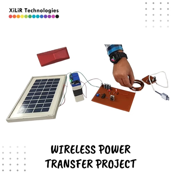
☀️ Solar-powered renewable energy source
⚡ Wireless power transfer without wires
🔁 CD4047 stable square wave generation
🔌 IRF540 MOSFET efficient switching
🧲 Inductive coupling using coils
📊 Practical efficiency analysis
🔋 Eco-friendly and low-cost system
📺 YouTube Video : Watch Full Video
- Description
- Customizations
- Reviews (0)
- Some Viva Questions n Answers
Description
Wireless Power Transfer System using Inductive Coupling enables contactless energy transmission through magnetic fields for efficient wireless charging of electronic devices. This circuit-based project uses oscillator, MOSFET driver, and transmitter–receiver coils to demonstrate real-time wireless power transmission with compact and efficient design.

—If coils are properly aligned → ⚡ Wireless Power Transfer Active
—If receiver enters magnetic field range → ✅ Power Transmission Successful
Introduction
#WirelessPowerTransfer #WirelessCharging #InductiveCoupling #ElectronicsProject #FinalYearProject
Award-Winning Capstone Project Idea: Wireless Power Transfer System using Inductive Coupling – Perfect for Final Year Engineering Students (CSE, ECE, EEE, Mechanical, Science)
Introduction
The transmission of electrical energy has traditionally relied on wired connections, which introduce limitations such as power losses, safety risks, mechanical wear, and restricted mobility. With the rapid advancement of portable electronics, electric vehicles, and smart systems, there is a growing demand for efficient, safe, and contactless methods of energy transfer. Wireless Power Transfer (WPT) has emerged as a transformative technology that enables electrical energy transmission without the need for physical conductors.
Wireless power transfer operates on the principle of electromagnetic induction, which is mathematically described by Faraday’s Law:
V = -N (dΦ/dt)
where V represents the induced voltage, N is the number of turns in the coil, and Φ denotes the magnetic flux. When an alternating current flows through the transmitter coil, it generates a time-varying magnetic field. This magnetic field induces an electromotive force in the receiver coil placed within its range, enabling wireless transfer of energy. The efficiency of this process depends on factors such as coil alignment, distance between coils, operating frequency, and coupling coefficient.
The concept of wireless energy transmission dates back to the late 19th century, when Nikola Tesla conducted pioneering experiments demonstrating the possibility of transmitting power through air using resonant inductive coupling. Although the technology was not widely adopted at that time due to practical limitations, recent advancements in power electronics and circuit design have enabled efficient and compact wireless power systems suitable for modern applications.
From a global perspective, energy efficiency is a critical concern. It is estimated that approximately 8–15% of total electrical energy is lost during transmission and distribution processes. Wireless power transfer systems, when optimised, can reduce connector-related losses, eliminate wiring complexities, and improve reliability in specific applications. Additionally, the removal of physical connectors minimises maintenance requirements and enhances safety, particularly in environments where wiring is difficult or hazardous.
The importance of wireless power transfer lies in its ability to provide seamless and convenient energy delivery. It eliminates the need for cables, reduces clutter, and enables operation in sealed, rotating, or inaccessible systems. This makes it highly suitable for next-generation technologies such as wearable electronics, biomedical devices, autonomous systems, and IoT-based smart environments.
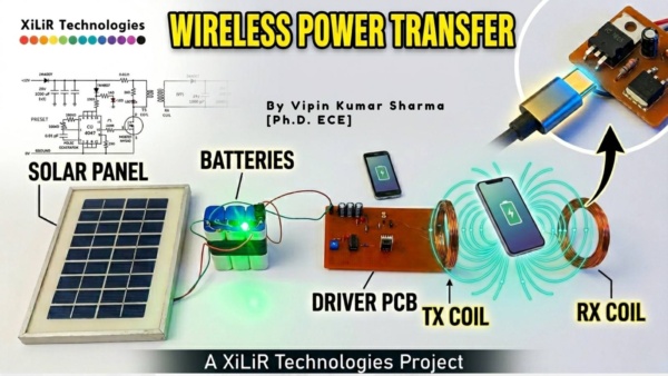
The proposed wireless power transfer system utilises an oscillator-based switching circuit with a MOSFET driver to generate high-frequency signals, which are applied to a transmitter coil. The resulting magnetic field induces electrical energy in the receiver coil, which is then rectified and filtered to obtain a usable DC output. The system demonstrates a compact, cost-effective, and efficient implementation of inductive wireless power transmission.
Wireless power transfer has a wide range of applications, including wireless charging of smartphones and laptops, electric vehicle charging systems, powering remote IoT sensors, biomedical implants such as pacemakers, industrial automation systems, and consumer electronics. Its ability to deliver power without physical contact makes it a key technology for future smart cities and advanced engineering systems.
Objectives
- To design and develop a wireless power transfer system using inductive coupling for contactless energy transmission between transmitter and receiver coils.
- To analyse the effect of coil alignment, distance, and coupling on the efficiency and stability of wireless power transmission.
- To implement an oscillator and switching circuit to generate high-frequency signals required for efficient magnetic field generation.
- To demonstrate practical wireless energy transfer by powering a low-voltage electronic load through induced voltage at the receiver side.
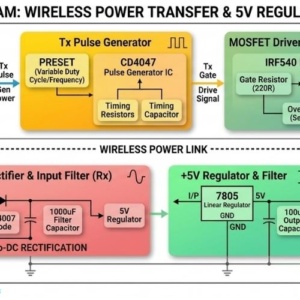
Block Diagram
![]()
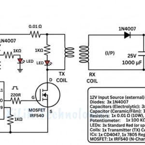
Original Circuit Diagram
![]()
Components Required
- CD4047 IC (Astable Multivibrator / Pulse Generator)
- MOSFET (IRF540 or equivalent)
- Transmitter Coil (Copper Winding Coil) 50 Turns
- Receiver Coil (Copper Winding Coil) 150 Turns
- Diodes (1N4007)
- Resistors 330 Ω, 1 kΩ, 10 kΩ , 100 kΩ390 kΩ220 Ω
- Capacitors0.01 µF, 1000 µF / 25V (multiple), 1000 µF / 35V (multiple),
- LED Indicator
- Zener Diode (5.1V or 5.6V)
- Voltage Regulator (5V, if used)
- Battery Rechargeable / DC Power Supply (12V)
- PCB / General Purpose Board
- Connecting Wires
- Load (LED / Small Device like mobile or module)
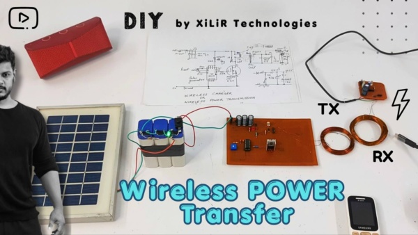
- Solar Panel (for alternative power source)
- Charging Module / Protection Circuit
- Mobile Phone (for demonstration of wireless charging) (not Provided with project)
Working Theory of Wireless Power Transfer System with Calculations
The proposed wireless power transfer system works on the principle of electromagnetic induction, in which electrical energy is transmitted from a transmitter coil to a receiver coil without direct wire connection. In this circuit, the CD4047 IC is used as a pulse generator, the IRF540 MOSFET acts as a switching device, and the transmitter and receiver coils transfer power through a changing magnetic field.
A DC supply is given to the transmitter side. The CD4047 is configured in astable mode and generates a square wave signal, which is fed to the gate of the IRF540 MOSFET. The MOSFET switches rapidly and causes current to flow through the transmitter coil, producing a time-varying magnetic field. When the receiver coil is brought near the transmitter coil, this magnetic field links with the receiver coil and induces voltage in it. The induced AC voltage is then rectified using a diode and filtered using a capacitor to obtain usable DC output.
The basic law governing this system is Faraday’s Law of Electromagnetic Induction:
V = -N (dΦ/dt)
where
V = induced voltage
N = number of turns
Φ = magnetic flux
This shows that the induced voltage depends directly on the number of turns in the coil and the rate of change of magnetic flux.
Given Specifications
Transmitter coil turns, Nt = 50
Receiver coil turns, Nr = 150
Transmitter voltage, Vt = 6 V
Receiver voltage, Vr = 8 V
Coil wire diameter = 0.3 mm
1. Turns Ratio Calculation
The turns ratio between receiver and transmitter coil is:
Turns ratio = Nr / Nt
Turns ratio = 150 / 50 = 3
So, the turns ratio is:
Turns ratio = 3 : 1
This means the receiver coil has three times more turns than the transmitter coil.
2. Ideal Voltage Ratio
In an ideal inductive system, the voltage ratio is proportional to the turns ratio:
Vr / Vt = Nr / Nt
Substituting your values:
Vr / 6 = 150 / 50
Vr / 6 = 3
Vr = 18 V
So, the ideal theoretical receiver voltage should be:
Ideal receiver voltage = 18 V
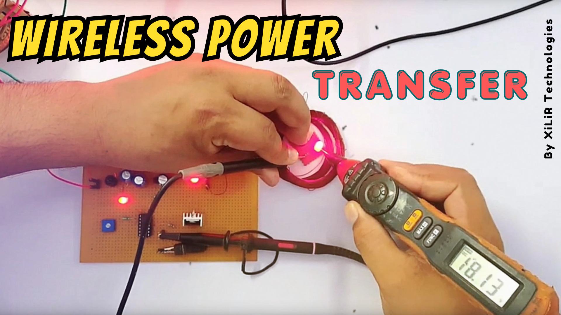
3. Actual Received Voltage
From your practical result:
Actual receiver voltage = 8 V
This means the system is not achieving the ideal 18 V because of practical losses such as:
-
air gap between coils
-
leakage flux
-
imperfect alignment
-
coil resistance
-
switching losses in MOSFET
-
rectifier diode losses
-
no magnetic core between coils
4. Voltage Transfer Efficiency
Since ideal voltage is 18 V and practical voltage is 8 V, the voltage transfer effectiveness can be estimated as:
Voltage efficiency = (Actual output voltage / Ideal output voltage) × 100
Voltage efficiency = (8 / 18) × 100
Voltage efficiency = 44.44 %
So, the practical voltage transfer relative to the ideal turns-ratio value is:
Voltage transfer efficiency = 44.44 %
5. Practical Gain over Input Voltage
Even though the ideal was 18 V, your actual measured output is still greater than input:
Voltage gain = Vr / Vt
Voltage gain = 8 / 6 = 1.33
So:
Voltage gain = 1.33 times
This means the receiver side voltage is about 33.3% higher than transmitter voltage, mainly because the receiver coil has more turns.
6. Frequency of CD4047
The oscillation frequency of CD4047 in astable mode is given by:
f = 1 / (4.4RC)
From your circuit image, the timing components appear approximately as:
R = 390 kΩ
C = 0.01 µF
Converting units:
R = 390 × 10^3 ohm
C = 0.01 × 10^-6 F = 10^-8 F
Now,
f = 1 / (4.4 × 390 × 10^3 × 10^-8)
f = 1 / (4.4 × 3.9 × 10^-3)
f = 1 / 0.01716
f = 58.27 Hz
So, the approximate oscillation frequency is:
f = 58.27 Hz
If your 100 kΩ preset is adjusted along with the resistor network, the actual frequency may vary around this value.
7. Ripple Voltage Formula
After the receiver coil induces voltage, the diode rectifies it and the capacitor smooths it. Ripple voltage is given by:
Vripple = Iload / (fC)
Since load current is not provided, numerical ripple cannot be calculated exactly. But this formula shows:
-
ripple decreases when capacitance increases
-
ripple decreases when frequency increases
Your use of 1000 µF capacitor helps reduce ripple and gives smoother DC output.
8. Coupling Statement
The coupling coefficient is:
k = M / √(L1L2)
where
M = mutual inductance
L1 = inductance of transmitter coil
L2 = inductance of receiver coil
Since inductance values are not given, exact coupling coefficient cannot be calculated. But from the measured output of 8 V instead of ideal 18 V, it is clear that the coupling is moderate and not ideal, which is normal in air-core wireless power transfer systems.
9. Effect of Number of Turns
Because:
Nr = 150 and Nt = 50
the receiver coil has more turns, so it can induce a higher voltage than the transmitter side, according to:
Vr ∝ Nr
This is why your receiver side is producing 8 V from a 6 V transmitter side, even under non-ideal conditions.
10. Effect of Wire Diameter
Your coil wire diameter is:
d = 0.3 mm
This affects current carrying capability and resistance. A 0.3 mm copper wire is suitable for small wireless power transfer setups because:
-
it allows compact winding
-
it reduces excessive coil bulk
-
it is suitable for moderate current
-
it helps maintain a reasonable number of turns
However, thinner wire has more resistance than thicker wire, which can increase copper losses and reduce efficiency.
Calculated Output Summary
Transmitter turns = 50
Receiver turns = 150
Turns ratio = 3 : 1
Input voltage = 6 V
Ideal output voltage = 18 V
Practical output voltage = 8 V
Voltage gain = 1.33 times
Voltage transfer efficiency = 44.44 %
Approximate CD4047 frequency = 58.27 Hz
Coil wire diameter = 0.3 mm
Final Working Theory Paragraph
The wireless power transfer system uses a CD4047 astable multivibrator to generate square wave pulses, which drive the IRF540 MOSFET. The MOSFET switches the transmitter coil and creates a changing magnetic field around it. The receiver coil, having 150 turns compared to 50 turns in the transmitter coil, captures this magnetic field and develops an induced voltage according to Faraday’s Law. For a transmitter voltage of 6 V, the ideal receiver voltage based on turns ratio is 18 V, whereas the practical measured output is 8 V due to coupling losses, leakage flux, and circuit losses. The practical voltage gain is 1.33, and the voltage transfer efficiency relative to the ideal case is 44.44%. The 0.3 mm coil wire provides a compact winding structure suitable for this low-power wireless charging system.
************************
wireless power transfer project, wireless charging system Arduino, inductive power transfer project, CD4047 wireless power system, IRF540 MOSFET project, transmitter receiver coil project, wireless electricity transfer, inductive coupling project, wireless charging using coils, engineering wireless power project, WPT system Arduino, low power wireless charging system, magnetic induction charging project, final year electrical project, electronics wireless power system, BTech project wireless charging, ECE power electronics project, IoT wireless charging system, smart wireless energy transfer, engineering project ideas, capstone project electronics, wireless power transmission system, solar wireless charging project, contactless power transfer system
🔹 Project Titles (Students Can Use)
- Design and Implementation of Wireless Power Transfer System Using CD4047 Oscillator and MOSFET Switching
- Low-Power Inductive Wireless Charging System Using Transmitter and Receiver Coils with Efficiency Analysis
- Wireless Energy Transfer System Using Magnetic Induction and MOSFET-Based Switching Circuit
- Efficient Contactless Power Transmission System Using CD4047 Multivibrator and Inductive Coupling
- Smart Wireless Power Transfer System for Low Voltage Applications Using Coil-Based Energy Transmission
- Wireless Charging Prototype Using Magnetic Field Induction with Performance and Efficiency Evaluation
- Design of Inductive Power Transfer System Using IRF540 MOSFET and Coil Optimization Techniques
- Compact Wireless Energy Transmission System Using Square Wave Oscillator and Coil Coupling
- Low-Cost Wireless Power Transfer Model Using Inductive Coupling and Oscillator-Based Switching
- Wireless Power Transmission System Using Coil Turns Ratio and Practical Efficiency Analysis
Contact us:
👨🏼🏭𝗩𝗶𝗽𝗶𝗻 𝗞𝘂𝗺𝗮𝗿 𝗦𝗵𝗮𝗿𝗺𝗮
Ph.D., M.Tech, B.Tech in ECE
🎓Lecturer 🚀#Researcher #Drone #Robotics
WhatsApp : https://wa.me/919810326343
✅🔥Follow us on
📺 YouTube 👥 Facebook 🐤 Twitter 📸 Instagram👨🏻🎓 LinkedIn
𝗔𝗯𝗼𝘂𝘁 𝗨𝘀 :
𝗫𝗶𝗟𝗶𝗥 𝗧𝗲𝗰𝗵𝗻𝗼𝗹𝗼𝗴𝗶𝗲𝘀™ is India’s 🔖Top rated & Leading R&D Company. It’s an ISO 9001:2008 Certified Company & Govt Approved under MCA & it was established in 2012.
🔧 Project Customizations (For Students)
Students can enhance or modify this project based on college syllabus, guide instructions, or personal interest.
Customizations help improve innovation, marks, and practical understanding.
Available Customization Options:
-
🌐 IoT/ AI/ ML Integration ( ThingSpeak, Blynk, Firebase, Web Dashboard etc. )
-
☀️ Solar Power Integration
-
🤖 Machine Learning / AI Modules
-
📡 GPS & GSM Based Tracking / Alerts
-
📟 Additional Sensors (as per application)
-
📲 Mobile App / Web Monitoring
-
📊 Advanced Data Logging & Graphs
-
⚙️ Hardware & Software Feature Modifications
-
🎯 Customization as per College or Guide Requirement
If you need any additional feature or modification,
📞 Contact us on WhatsApp and share your requirement.

Early Project Booking Recommended
Early Project Booking – Strongly Recommended
Students are advised to book their final year or semester project early, even with just a title or brief idea. Early booking helps us reserve your preferred topic, start documentation, diagrams, code planning, and component preparation in advance, and provide timely academic guidance.
You will receive complete documentation (abstract, report, block diagram, circuit, code explanation) well before submission. The working hardware kit will be delivered as per your college schedule. PPTs for reviews, viva, or seminars will be prepared on request.
Book early → Stay stress-free → Focus on learning.
Contact us with just the project title—we’ll handle the rest.
Be the first to review “Solar based Wireless Power Transfer (WPT) Project”
Questions n Answers
👉 “Why CD4047 is used?”
It works as an astable multivibrator to generate a stable square wave, which is required to drive the switching circuit efficiently.👉 “Why MOSFET IRF540?”
It has high switching speed and low ON resistance, allowing efficient power transfer with minimal losses.👉 “Why high frequency signal is required?”
Higher frequency improves magnetic coupling and increases induced voltage in the receiver coil.
👉 “Why coil is used?”
Coils create and receive magnetic fields, enabling energy transfer through electromagnetic induction.
👉 “Why two coils (TX & RX)?”
One coil generates the magnetic field (transmitter), and the other captures it (receiver) to convert it back into electrical energy.👉 “Why diode (1N4007) is used?”
It rectifies the induced AC signal into DC for powering electronic loads.
👉 “Why capacitor is used?”
Capacitors filter ripples and provide smooth DC output after rectification.
👉 “Why Zener diode is used?”
It regulates and limits the output voltage to protect the load from overvoltage.
👉 “Why LED is used?”
It acts as an indicator to show successful power transfer and output availability.
👉 “What is the main principle?”
Electromagnetic induction based on Faraday’s Law.
👉 “What happens if coils are misaligned?”
Coupling reduces, resulting in lower induced voltage and reduced efficiency.
👉 “What type of coupling is used?”
Inductive coupling.
👉 “Why no direct wire connection?”
To achieve contactless power transfer, improving safety and flexibility.
👉 “What are the losses in this system?”
Copper losses, magnetic leakage, switching losses, and alignment losses.
👉 “How can efficiency be improved?”
By improving coil alignment, increasing frequency, using better core material, and reducing distance between coils.
👉 “What is the limitation of this system?”Limited range and reduced efficiency over distance.
👉 “Real-life applications?”
Wireless charging, EV charging, biomedical implants, IoT devices.


Reviews
There are no reviews yet.