
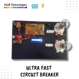
Ultra Fast Electronic Circuit Breaker for Overload Protection

Original price was: ₹10,500.00.₹7,350.00Current price is: ₹7,350.00.
When the power supply is overloaded, a circuit breaker is an automatically operated switch that shuts down the power supply.
The current Flowing through the CTs, which are connected in series with the load, is what triggers the trip.
The goal of this study was to build a power supply that shuts down when it becomes overloaded by employing a super-fast electronic circuit breaker.
✨ Highlights
📏 Real-Time Current Monitoring
⚡ Ultra-Fast Electronic Tripping Mechanism
🔁 MOSFET Driven Relay Switching
📟 16×2 LCD Live Status Display
🔌 Manual Reset & Control Switches
💡 Dual Bulb Load Demonstration
🛡️ Improved Protection over Traditional MCB
- Description
- Customizations
- Whats Included !
- YouTube
- FAQs
Description
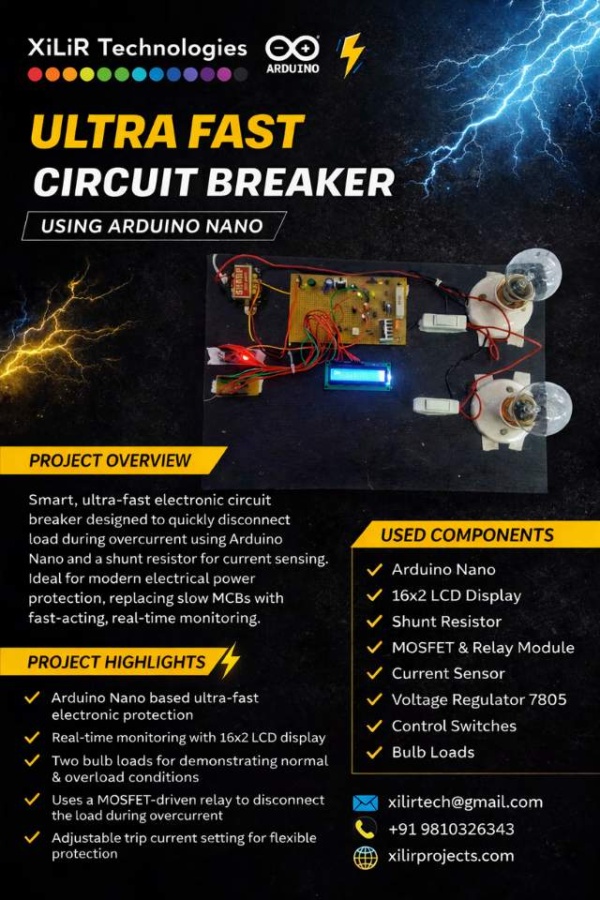
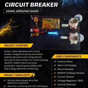
INTRODUCTION
Electrical power systems require reliable and fast protection mechanisms to prevent damage caused by overloads and short circuits. Conventional protection devices such as Miniature Circuit Breakers (MCBs) operate on a thermal bimetallic strip mechanism, where tripping time depends on the percentage and duration of overload. Although effective for general-purpose protection, MCBs exhibit comparatively slower response times, making them less suitable for sensitive electronic loads and modern automation systems that demand rapid fault isolation.
To overcome these limitations, this project presents an Ultra-Fast Electronic Circuit Breaker (ECB) using an Arduino microcontroller. Unlike traditional thermal breakers, the proposed system continuously monitors load current using a sensing element (low-value shunt resistor/current sensor). The voltage drop developed across this element, proportional to the load current, is measured and processed by the microcontroller. When the sensed current exceeds a predefined threshold, the controller instantly triggers a relay through a MOSFET driver circuit to disconnect the load.
The system incorporates a 16×2 LCD display for real-time monitoring of current status and fault conditions. Manual control switches are provided for resetting and testing purposes. Two bulb loads are used to demonstrate normal and overload operating conditions. A regulated power supply section consisting of a transformer, bridge rectifier, filter capacitor (1000µF), and LM7805 voltage regulator provides stable DC power to the control circuitry.
The proposed electronic circuit breaker offers several advantages over conventional MCBs, including:
-
Faster tripping response (milliseconds range)
-
Adjustable trip settings through software
-
Improved protection for sensitive electrical and electronic equipment
-
Real-time status indication via LCD
-
Reset capability without component replacement
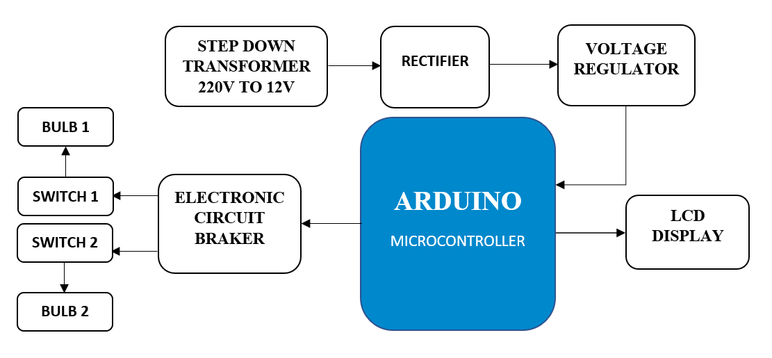
BLOCK DIAGRAM
HARDWARE COMPONENTS
- ARDUINO
- STEP DOWN TRANSFORMER
- RECTIFIER
- VOLTAGE REGULATOR
- ELECTRONIC CIRCUIT BREAKER
- SWITCH (2X)
- BULB (2X)
- LCD DISPLAY
- JUMPER WIRES
SOFTWARE
- ARDUINO IDE
- EMBEDDED C
METHODOLOGY
The methodology of the proposed Ultra-Fast Electronic Circuit Breaker using Arduino Nano is described in the following steps:
-
System Design and Planning
The overall system is divided into functional blocks including power supply unit, current sensing unit, microcontroller unit (Arduino Nano), driver circuit (MOSFET + relay), load section (two bulbs), LCD display, and control switches. The trip current threshold is predefined in the Arduino program. -
Power Supply Unit
An AC supply is stepped down using a transformer, rectified using a bridge rectifier, and filtered using a 1000µF capacitor. The LM7805 voltage regulator provides a stable 5V DC supply for the Arduino Nano, LCD, and other control circuitry. -
Current Sensing Mechanism
A low-value shunt resistor (or current sensing element) is connected in series with the load. The voltage drop across this resistor, which is proportional to the load current, is fed to the analog input pin of the Arduino Nano for monitoring. -
Signal Processing and Comparison
The Arduino Nano continuously reads the analog voltage corresponding to load current. The measured value is compared with the predefined current limit programmed in the microcontroller. If the measured current exceeds the set threshold, it is identified as an overload condition. -
Tripping Mechanism
Upon detecting overload, the Arduino sends a signal to a MOSFET driver circuit which energizes or de-energizes a relay. The relay instantly disconnects the load from the supply, thereby protecting the system from damage. -
Display and Indication
A 16×2 LCD is used to display real-time information such as normal operation, overload condition, and trip status. This improves monitoring and user interaction. -
Manual Reset and Testing
Switches are provided for resetting the breaker after a trip condition and for testing the system. Once the fault is cleared, the system can be manually reset to restore power. -
Testing and Validation
Two bulb loads are connected to simulate normal and overload conditions. The response time and proper tripping action are observed and verified to ensure fast and reliable operation
Titles Suggestions:
• Ultra Fast Electronic Circuit Breaker Using Arduino Nano
• Smart Overcurrent Protection System
• Digital Circuit Breaker Project for Final Year
• Arduino Based Electronic Switching Protection
• Microcontroller Based Load Protection System
#UltraFastCircuitBreaker #ArduinoNano #ElectricalProject #FinalYearProject
#OvercurrentProtection #EngineeringProject #SmartProtection
Ultra fast electronic circuit breaker using Arduino Nano, Arduino Nano based circuit breaker project, microcontroller based overcurrent protection system, smart electronic circuit breaker project, digital circuit breaker using ATmega328P, Arduino overload protection system, fast acting electronic circuit breaker, electronic MCB replacement project, Arduino Nano electrical protection project, overcurrent detection using Arduino, relay based circuit breaker system, MOSFET driver circuit for relay, current sensing using shunt resistor Arduino, 16×2 LCD display Arduino project, electrical engineering final year project circuit breaker, diploma electrical project on circuit breaker, smart power protection system Arduino, electronic circuit breaker with LCD display, Arduino based load monitoring system, hardware project on electronic circuit breaker.
========================
👉🚀 Don’t forget to SUBSCRIBE for more Science/ Diploma/ Engineering Projects !
========================
🙌 Need custom features or upgrades? Just ask — we’re happy to help! 🙌
✔ Cash on Delivery Available (India Only)
✔ Safest, Secure & Trackable delivery across Globally.
⭐ Trusted by 20,50,000+ Students, Teachers & Innovators
🏆 Serving the academic & research community since 2012
📞 To Buy/ Make this project with training
• • • • • • • • • • • • • • • • • • • • • • •
Contact us:
👨🏼🏭 Dr. Vipin Kumar Sharma
🎓 Ph.D., M.Tech, B.Tech (ECE), C.E, D.E NS.
👨🏫 Lecturer | 🚀 Researcher | 🤖 Robotics | 🌐 IoT
📱 WhatsApp (Direct Support) Hindi/ English Language
• • • • • • • • • • • • • • • • • • • • • • •
📍𝗔𝗯𝗼𝘂𝘁 𝗨𝘀 :
𝗫𝗶𝗟𝗶𝗥 𝗧𝗲𝗰𝗵𝗻𝗼𝗹𝗼𝗴𝗶𝗲𝘀™ is India’s 🔖Top Rated & Leading Research & Development Company. It’s an ISO 9001:2008 Certified Company & Govt Approved under MCA & it was established in 2012.
🔥Hey !, Follow us on
📺 YouTube 👥 Facebook 🐤 Twitter 📸 Instagram👨🏻🎓 LinkedIn
• • • • • • • • • • • • • • • • • • • • • • •
🔧 Project Customizations (For Students)
Students can enhance or modify this project based on college syllabus, guide instructions, or personal interest.
Customizations help improve innovation, marks, and practical understanding.
Available Customization Options:
-
🌐 IoT/ AI/ ML Integration ( ThingSpeak, Blynk, Firebase, Web Dashboard etc. )
-
☀️ Solar Power Integration
-
🤖 Machine Learning / AI Modules
-
📡 GPS & GSM Based Tracking / Alerts
-
📟 Additional Sensors (as per application)
-
📲 Mobile App / Web Monitoring
-
📊 Advanced Data Logging & Graphs
-
⚙️ Hardware & Software Feature Modifications
-
🎯 Customization as per College or Guide Requirement
If you need any additional feature or modification,
📞 Contact us on WhatsApp and share your requirement.

Early Project Booking Recommended
Early Project Booking – Strongly Recommended
Students are advised to book their final year or semester project early, even with just a title or brief idea. Early booking helps us reserve your preferred topic, start documentation, diagrams, code planning, and component preparation in advance, and provide timely academic guidance.
You will receive complete documentation (abstract, report, block diagram, circuit, code explanation) well before submission. The working hardware kit will be delivered as per your college schedule. PPTs for reviews, viva, or seminars will be prepared on request.
Book early → Stay stress-free → Focus on learning.
Contact us with just the project title—we’ll handle the rest.
Whats Included !
No branding, handmade and different look as required by students.
WhatsApp : https://wa.me/919810326343
————————————
🔖 What you’ll get when you order this Project !
💯 Fully Assembled & Working Project.
🛠️ The project can be disassembled and reassembled if needed, making it easier to show progress-wise demonstrations to your guide.
📘 Includes Synopsis, Report, PPT & more.
📊 Block Diagram & Circuit Diagram – With explanations.
📦 Component Specs List.
⚙️ Working Principle Explained.
📑 Datasheets of All Components.
💻 Arduino Code + Training.
🧾 Bill of Materials (BOM) – Every item listed.
🔌 Complete Interfacing Guide – Learn how each part is connected.
🚚 Cash on Delivery Available – Safe & Secure delivery.
🎓 Viva Q&A Guidance – Be 100% ready for your Viva.
❓Need anything, Just ask us – we’re here to help! 🙌
————————————
🥇 Trusted by 20,50,000+ Students / Teachers & Innovators.
Additional Services you can buy :
Research paper, Review paper,
Plagiarism free Report with Turnitin report,
internship, industrial training/ project etc.
https://youtu.be/9u4V5cePphQ
FAQs